Week Eight
NOT SHOCKING PEOPLE
Steps of Rube Goldberg Circuit
Figure 1: Video of Rube Goldberg Function
Circuit Explanation

Figure 2: Step 1: The Pressure sensor is pressed by a weighted object.

Figure 3: Step 2: The light of the LED connected to the OR gate turns on, informing the user that we must begin applying heat to the temperature sensor.

Figure 4: The gate mentioned in step 2

Figure 5: Image of AND gate on bottom and driver on top. The and gate inputs are connected to the relay input is parallel and the pressure sensor. When both of these are active the counter will begin to function.

Figure 6: Step 3: The heat provided to the temperature sensor allows for a voltage and current to flow into the ompamp, amplifying the current, allowing the relay to switch on.
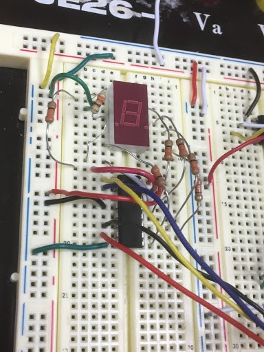
Figure 7: Step 4: Once the and gate is satisfied with two active inputs, then the driver begins to send signals to the counter, which then sends signal to the digital display, starting the count up from 0 to 9 and then repeating.

Figure 8: Step 5: Once the relay is active, current is applied to a motor which spins this mechanical apparatus, knocking over something important and making something happen for somebody else.
Struggles

One struggle we faced was getting the relay to switch while connected to the temperature sensor. We noticed that there was not enough voltage going between the temperature sensor output to the relay (only 1V). We first tried to fix this with a 741 amplifier being placed between the two, but that did not amplify the current enough to switch on the relay. Instead, we used an opamp to amplify, which introduced our next problem.
Another struggle we faced was applying the proper gain to the opamp to switch the relay on, even though we knew it could work, we were concerned why it wasn't. What we had found was that we were applying too small of a voltage to the voltage input to power the opamp. After increasing the opamp voltage to 20 V, the amplified voltage and current was able to reach the appropriate amplitude to switch the relay on.
My group faced a similar issue with finding the correct gain for the circuit along with inputting the correct voltage to power the OPAMP. How did you discover that the Opamp needed more power to function, and di this completely fix the problem?
ReplyDeleteWe learned by the direction of Professor Kaya that in order for the higher voltage to be generated by the OPAMP, it needed to be supplied with a greater than needed voltage, as the OPAMP can not generate a voltage output greater than what is supplied as power for the OPAMP.
DeleteNice Rube Goldberg. Clear photos and videos, but you are missing the captions. I like how you used the forcing resistor. We tried to use it, but we couldn't find anything that is heavy enough to decrease resistance.
ReplyDeleteWell done.
We will add captions. It does take a good amount of weight. For example we used an external battery source for ours which has a significant amount of weight concentrated into one area, which allowed for proper function of the force resistor.
DeleteWe also struggled with getting a high enough voltage to trigger the relay but we went at it another way we increased the voltage to the opamp so that the voltage from the temperature sensor didn't need to be as high. You want to try and explain the circuit better and add captions. Other than that very cool Rube Goldberg machine.
ReplyDeleteThank you. We will explain better.
DeleteOur group had the same issue finding the proper gain but we used two resistors which were over 500 ohms and that didn't solve the problem, so we figured out that we can increase the voltage on the operational amplifier and that was enough to switch the relay. I like how you include a lot of photos in the blog but they need captions. Also, putting some explanation with the pictures will be helpful to show how you set up your circuit. Your Rube Goldberg was great.
ReplyDeletethank you for your comment
Deletewe added the captions
Your Rube Goldberg project looks like you had a lot of fun with it! Good job on finding enough Lego like pieces to make the rotating arm. It takes a lot of time to build them, and good I with making it hit something else instead of just having it rotate. Getting the temperature sensor to work is a lot of work because you have to hold the hair dryer for so long on your sensor before it does anything.
ReplyDeletethank you for your comment
DeleteThis comment has been removed by the author.
ReplyDeleteGood job. I like your RG contraption.
ReplyDeleteNice work getting the large motor working! Our group struggled a lot trying to get that beast to spin. I really like the steps put into your blog, very through!
ReplyDelete