Monday, January 30, 2017

Week 4

Week 4

Not Shocking People

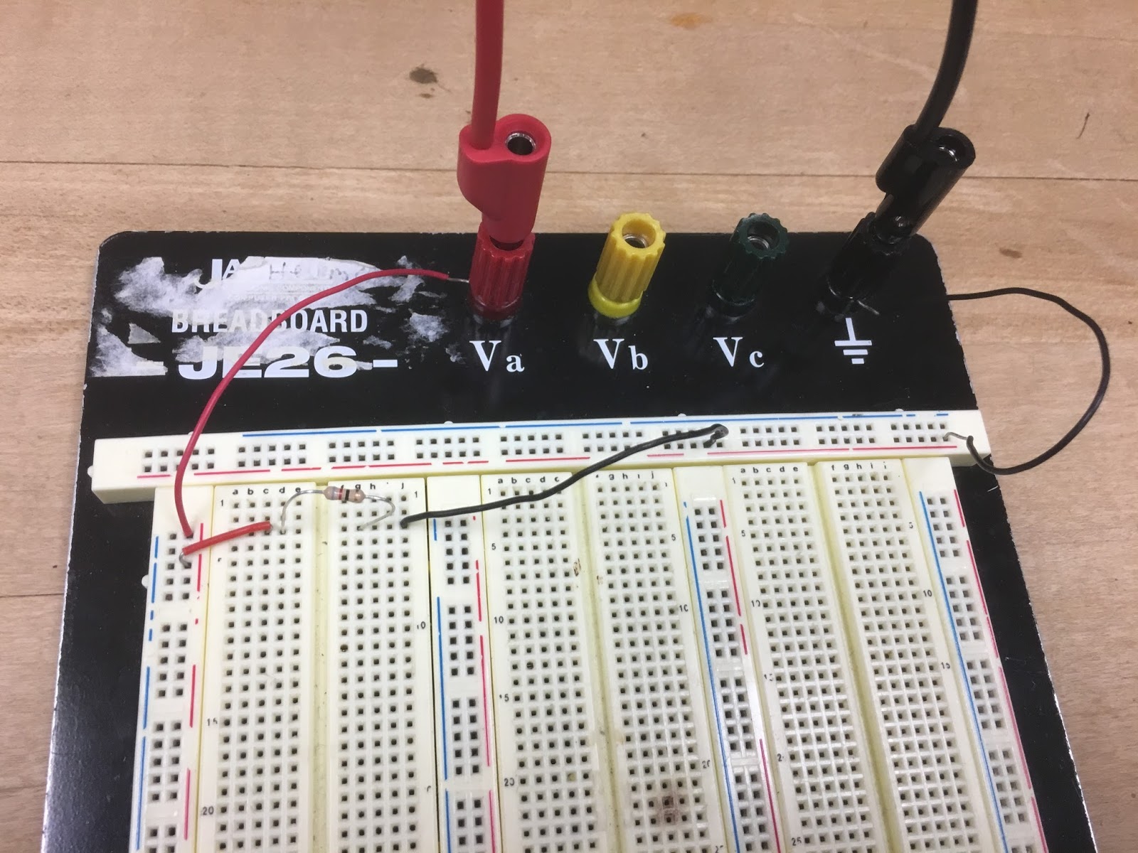
1. (Table and graph) Use the transistor by itself. The goal is to create the graph for IC (y axis) versus VBE (x axis). Connect base and collector. DO NOT EXCEED 1 V for VBE. Make sure you have the required voltage value set before applying it to the base. Transistor might get really hot. Do not TOUCH THE TRANSISTOR! Make sure to get enough data points to graph. (Suggestion: measure for VBE = 0V, 0.5V, and 1V and fill the gaps if necessary by taking extra measurements).  

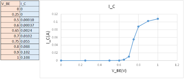
Figure 1& 2: Corresponding between the table and the line graph,  is the measurements of V_BE(V) and I_C(A). As can be seen, as the Voltage of V_BE is increased little occurs till 0.6V, wherein which the current of I_C is allowed to begin to flow, and later plateaus at max current.  

2. (Table and graph) Create the graph for IC (y axis) versus VCE (x axis). Vary VCE from 0 V to 5 V. Do this measurement for 3 different VBE values: 0V, 0.7V, and 0.8V.

Figure 3 & 4: The corresponding images of the table and graph show the measurements of the current I_C(A) while each separate voltage V_BE(V) is applied. It is shown that as the voltage is increased (V_BE), more current is allowed to flow. As for V_CE, as it is increased, more current is pushed through due to the magnitude of the Voltage.

3. (Table) Apply the following bias voltages and fill out the table. How is IC and IB related? Does your data support your theory?

Figure 5: The measurements of current through I_C and I_B while increasing voltage through V_BE(V)

I_C and I_B are related in the sense where after a certain voltage is applied at V_BE(V), the current through I_B will be able to flow to a significant degree, and the current from the collector will be able to flow at significant quantities, as you can see as the voltage is increased at V_BE the current at I_B increases to a significant degree of mA's and I_C is current is increased significantly.

4. (Table) Explain photocell outputs with different light settings. Create a table for the light conditions and photocell resistance.

The more light that is applied to the photoresistor, the less resistance it produces. For example, with light in a typical florescent classroom, the current is measured highest at 3.8mA. As less light (photons) are allowed to enter the photoresistor, the more resistance is applied, forcing the current to be lower and lower. \
Figure 6: Current and Resistance Measurements of the photoresistor as less and less light is applied.


5. (Table) Apply voltage (0 to 5 V with 1 V steps) to DC motor directly and measure the current using the DMM.

Figure 7: Measured Current through a DC motor

6. Apply 2 V to the DC motor and measure the current. Repeat this by increasing the load on the DC motor. Slightly pinching the shaft would do the trick.

Figure 8: Current measured whilst pressure is added to the motor (Nick pinching).

7. (Video) Create the circuit below (same circuit from week 1). Explain the operation in detail.


Figure 9: Video explaining the operation of the circuit supplied.


8. Explain R4’s role by changing its value to a smaller and bigger resistors and observing the voltage and the current at the collector of the transistor.

The purpose for R4 is to dictate the voltage that goes through the transistor. If there was too small or no resistor at R4, the current entering the transistor would be too high and could short the transistor. If the resistance is too high, then the current would not sufficiently flow to the Motor to make it run.

9. (Video) Create your own Rube Goldberg setup.

Figure 10: Video of initial Rube Goldberg setup. 

The circuit being displayed is one that would have made this function properly work if we had transistors and photoresistors that could handle a higher voltage needed to make the 12V DC Motor run. The circuit setup is directly similar to that of the previous problem (#7). However, not enough current could be moved through the transistor to make the motor run. This could be solved by getting a stronger power source and transistor, or to use relays.

Sunday, January 29, 2017

Week Three


Week 3

Not Shocking People

1. Compare the calculated and measured equivalent resistance values between the nodes A and B for three circuit configurations given below. Choose your own resistors. (Table)

Figure 1: Equivalent Resistance Comparison Table


2. Apply 5V on a 120 Ω resistor. Measure the current by putting the multimeter in series and parallel. Why are they different?

When measuring the current in series with the DMM, we measured 39.4 mA. When measuring current in parallel, we read a measurement of 0 Amps, but the machine was also registering an overload. This is because when we connect the DMM in parallel, we are essentially shorting the current that would have flown through the resistor, as it is now running through the DMM which is acting as 0 Ω resistor.

3. Apply 5 V to two resistors (47 Ω and 120 Ω) that are in series. Compare the measured and calculated values of voltage and current values on each resistor.

The current on both resistors are the same at around 29 mA. The voltage on the 47 Ω resistor is 1.38V. The voltage on the 120 Ω resistor is 3.58V. 

4. Apply 5 V to two resistors (47 Ω and 120 Ω) that are in parallel. Compare the measured and calculated values of voltage and current values on each resistor.

The voltage on the 47 Ω resistor is 4.94V. The current on the 47 Ω resistor is 92.8mA. The voltage on the 120 Ω resistor is 4.94V. The current on the 120 Ω resistor is 39.4mA.

5. Compare the calculated and measured values of the following current and voltage for the circuit below: (breadboard photo)

Figure 2: Circuit Configuration for Problem 5


a. Current on 2 kΩ resistor,

Figure 3: Measuring the 2kΩ resistor, finding 2.03 mA


b. Voltage across both 1.2 kΩ resistors.

Figure 4: Measuring a 1.2kΩ resistor, finding .853 V

Figure 5: Measuring a 1.2kΩ resistor, finding .722 V


6. What would be the equivalent resistance value of the circuit above (between the power supply nodes)?

2519.7Ω

7. Measure the equivalent resistance with and without the 5 V power supply. Are they different? Why?

The resistance is 554 Ω without the power supply. The DMM was not able to read the resistance while the power source was connected. This is because the DMM acts as a voltage source itself. When you apply an additional source to the circuit, you confuse the DMM. 

8. Explain the operation of a potentiometer by measuring the resistance values between the terminals (there are 3 terminals, so there would be 3 combinations). (video)

Firgure 6: Explaining the operations of a potentiometer 


9. What would be the minimum and maximum voltage that can be obtained at V1 by changing the knob position of the 5 KΩ pot? Explain.


The minimum voltage that could be obtained was 0V as the potentiometer was turned fully towards the ground terminal, which meant all of the resistance was concentrated between voltage input and V1 terminal, causing the V1 to be 0.  The maximum voltage that could be obtained was 5 V as the potentiometer was turned fully towards the voltage input terminal, causing all of the resistance to be between the ground and the V1 terminal, allowing V1 to be 5V.

10. How are V1 and V2 (voltages are defined with respect to ground) related and how do they change with the position of the knob of the pot? (video)
Figure 7: Explaining the relationships between measuring V1 and V2


11. For the circuit below, YOU SHOULD NOT turn down the potentiometer all the way down to reach 0 Ω. Why?

This is because when turning the potentiometer all the way down, this will cause the circuit to short through the potentiometer, frying it.


12. For the circuit above, how are current values of 1 kΩ resistor and 5 KΩ pot related and how do they change with the position of the knob of the pot? (video).

Figure 8: Explaining how the currents are related, as well as the effect of the knob position


13. Explain what a voltage divider is and how it works based on your experiments.

A voltage divider divider is a device with two resistors in series with an input. It can convert a large voltage into a small one, making the output smaller than the input. For this experiment the potentiometer works as a voltage divider. By turning the knob we can adjust the output voltage. When the knob is turned completely towards the input, the voltage drop is near zero, as the current is able to bypass the resistor, or short. When the knob is turned completely towards the ground, the voltage drops to zero, due to the entire interior resistor being utilized. 

14. Explain what a current divider is and how it works based on your experiments.

A current divider is a device that uses to parallel resistors to divide current from a power source. This allows for different amounts of current to be applied to different parts of the circuit. For our experiment we connected a current divider(potentiometer) in parallel with a 1k resistor. This allowed for different amount of current to pass through the potentiometer as we increased and decreased the resistance. 

Wednesday, January 18, 2017

Week Two

Week Two

Not Shocking People

1. What is the role of A/B switch? If you are on A, would B still give you a voltage?

The A/B switch is used to change the voltage and current display to match that of what is being produced from the corresponding source. Additionally, when one (A or B) is selected, the user will be able to change the current or voltage produced from the source.

In matters of dual use, when A is currently selected and displayed, B will still be producing the same current and voltage that was selected whilst B was selected.

2. In each channel, there is a current specification (either 0.5 A or 4 A). What does that mean?

The 0.5 or 4 A specification represented over each channel, details the maximum current that may be produced by that channel.


3. Your power supply has two main operation modes for A and B channels; independent and tracking. How do those operation work?

Independent: When the independent operations is enabled, the A and B sources are separate, being able to be independently altered.
Tracking: Series: When the series tracking operation is enabled, the positive terminal of the B source is connected to the negative source of A, and vice versa, putting them in series, allowing for the user to connect leads to either the positive A terminal and negative B terminal, or the negative A terminal and the positive B terminal. This allows the user to draw more voltage.
Parallel: When the parallel tracking operation is enabled, the two sources are connected in parallel, allowing the user to draw larger currents


Fig. 1: Independent and Tracking (Power Source)
Showing how the operations of the Independent and Tracking methods work


4. Can you generate +30 V using a combination of the power supply outputs? How? (Photo)

Both voltage sources are set independently to 15 V, and are then connected in series to one another. The positive lead is connected to the positive terminal of A, and the negative lead is connected to the negative terminal of B.
Fig. 2: Result measurement of setup for +30 V


5. Can you generate -30 V using a combination of the power supply outputs? How? (Photo)

Both voltage sources are set independently to 15 V, and are then connected in series to one another. The positive lead is connected to the negative terminal of A, and the negative lead is connected to the positive terminal of B.

Fig. 3: Result measurement of setup for -30 V


6. Can you generate +10 V and -10 V at the same time using a combination of the power supply outputs? How? (Photo)

We made each source independently produce 10 volts.With both examples we connected the negative DMM lead to the ground.
Fig. 4: Result measurement of setup for -10 V
 With the B channel, we connected the positive DMM lead to the positive B terminal, producing a -10 V measurement.

Fig. 5: Result measurement of setup for +10 V
With the A channel, we connected the positive DMM lead to the negative A terminal, producing a 10 V measurement.

7. Apply 5V to a 100 Ω resistor and measure the current by using the DMM. Compare the reading with the current meter reading on the power supply. At what angle of the current knob makes the LED light on? If you keep on decreasing the current limit, what happens to the voltage and current?

Fig. 6: Results of decreasing current max, working with LED


8. Where is the fuse for the power supply? What is it for?

It is on the back panel as part of the power supply cable input area. It is used to cut off power to the machine if something is wrong within the machine or if too much current is being applies to the machine. 


9. Where is the fuse for the DMM? What is it for?

It is the largest of the circles on the bottom left of the input/output board. (On ours, labeled FUSED 2 A MAX) It is used to shut off the machine if something is wrong with the machine, or if there is too much current being applied to the machine.

10. What is the difference between 2W and 4W resistor measurements?

2 W and 4 W are used to represent 2 wire and 4 wire resistance measurements. The difference between the two is that with a 4 wire resistor the test lead resistance is reduced, allowing for lower resistances to be measured. The 2W can handle up to 100 ohms whilst 2W can handle 1000 ohms.


11. How would you measure current that is around 10 A using DMM?


You change the position of the input (red) lead to the 10 A input on the handheld DMM (12 on the BK PRECISION model), and change the reading/display method dial to A (not mA).

Friday, January 13, 2017

Week One

Not Shocking People: Lesson 1


Week 1

1. What is the class format?   The class is set up over three days: Monday, Wednesday, and Friday. 

Monday:

Class starts discussing the take home quiz assigned the previous Monday. The lab for that week is then discussed with the class, led by Professor Tolga Kaya, from which the students separate into their separate groups of two and begin work on the lab till the end of class, during such time work stations are cleaned up and work is wrapped up.

Wednesday: 

The class spends this day working on the lab discussed on Monday.

Friday:

This day is spent discussing and commenting on each groups blog.

2. What are the important safety rules?

Any and all safety rules established by an instructor/supervisor/company/ext. should be followed and are all important to be followed for the safety of the operator and all others who may be in contact and/or in the immediate vicinity of anything being worked with. With this in mind, for the class environment of EGR 393, all the rules established by Professor Tolga Kaya in his syllabus should be followed with equal necessity and promptness.

For arguments sake, there will be a few named as the most important:

  • When working with an experiment or project, there must be no power applied while it is being assembled or dissembled, and all high voltage points must be discharged to ground with an insulated jumper.
  • Do not work alone when working with energized equipment.
  • Do not simultaneously touch two pieces of equipment. 
  • Do not wear accessories that have metal components(i.e. ring, watch).
  • If standing on a damp or metal floor or have wet hands, do not touch electrical equipment. 
  • Know where the fire extinguisher, med kit, and phone are in case of emergencies.

3. Does a circuit kill?

Yes, a circuit that has a current between 0.1 to 0.2 Amperes will kill. Current above 0.2 have the potential to kill but will more likely lead to severe burns and respiratory failure(stop breathing), which can both lead to death.

4. How do you read color codes?


5. What is the tolerance?

Tolerance is a measure of the variation from a specified value given on a piece of equipment. For example,

6. Prove all your resistors are within the tolerance range.
The represented resistance in the color code compared to the measured resistance, and the actual deviation of the measured value compared to the represented value.

7. What is the difference between measuring the voltage and current using a DMM? Why?

Apart from needing the positive lead being placed in a separate input when measuring current or voltage, when measuring voltage through a resistor, the leads must be placed on both ends of a resistor while the circuit is live. However, when measuring current, one must disconnect power and break the circuit, connecting one lead to each end of the break, removing hands, and turning on the power supply.

8. How many different voltage values can you get from the power supply? Can each one of them be changed to any value?

You can supply three different voltage values at one time with the power supply provided in Professor Kaya's class. Two of the supplies, the ones labeled A and B, can be changed from 0V to 25V. 

9. Practice Circuit Results

Voltage measurement 

Voltage measurement connection


Current measurement 


Current measurement connection

10. How do you experimentally prove Ohm's Law? 

Ohm's Law: V=I*R => R=V/I
With the resistance predicted to be a fairly constant value, the idea is that as we increase the voltage , the current should go up proportionally, meaning that according to Ohm's law, the resistor value never changes.
We measured the current of a circuit using two resistors at five different voltages. The idea is that the current will rise as the voltage does, making it so that the calculated resistance stays the same. As you can see by our measurements, the current does increase, and when seeing the calculated resistance values, the resistance remains within tolerance.

11. Rube Goldberg circuit

12. Draw the circuit diagram for the Rube Goldberg machine set-up.

(Made using Digi-Key)

13. How can you implement this setup into a Rube Goldberg machine? 

When light is shined on the photo-resistor, the motor will run making a fan spin. The fan will blow over the first of many dominoes that will trigger another section of the Rube Goldberg machine.